


Catalytic Reforming
reference information
Process of catalytic reforming of gasoline fractions (gasoline reforming) is one of the most important processes of the modern oil-refining and petrochemical industry. Reforming process is intended for production of high-octane components of automobile gasolines and light aromatic hydrocarbons – benzene, toluene and xylenes. Very important product of reforming process is hydrogen gas with high content of hydrogen, used for hydrotreating wide range of oil fractions, for hydrocracking of heavy oil fractions and other hydrogenation processes.
Catalytic reforming process is a difficult chemical process. First, it is due to chemical composition of initial process feed – various gasoline fractions. More than 150 hydrocarbons are included in so-called wide fraction of gasoline. These are hydrocarbons of three main groups: paraffin normal and iso-hydrocarbons, naphthenic hydrocarbons with five-membered and six-membered cycles with one or several replacing alkyl groups and aromatic hydrocarbons which are usually represented by benzene, toluene, xylenes and negligible quantity of heavier alkylbenzenes. Normal hydrocarbons and monomethyl-substituted structures prevail among paraffins. Naphthenes are represented by homologs of cyclopentane and cyclohexane.
Scientific bases of catalytic reforming process were prepared by works of the Russian scientists. Thus, in 1911 N. D. Zelinsky showed possibility of dehydrogenation of six-membered naphthenic hydrocarbons at temperature above 300 °C over platinum and palladic catalysts quantitatively, practically without side reactions. In the same year dehydrogenation of naphthenic hydrocarbons during their contact with metal oxide was carried out by V. N. Ipatiev and N. Dovgelevich. In 1936 in the USSR reaction of direct dehydrocyclization of paraffin hydrocarbons into aromatic ones was found in three laboratories simultaneously. B. L. Moldavsky and G. D. Kamusher in GIVD (State scientific and research chemical institute of high pressure) carried out dehydrocyclization of paraffins on chrome oxide at temperature of 450-470 °C. V. I. Karzhev, M. G. Severiyanova and A.N. Siova in VNIGI (All-Soviet Union scientific and research institute of synthetic liquid fuel) observed reactions of dehydrocyclization of paraffins over copper-chromium catalyst at temperature of 500-550 °C. In Moscow State University B.A. Kazansky and A.F. Plate showed possibility of dehydrocyclization of paraffin hydrocarbons in the presence of platinized coal at temperature of 300-310 °C.
Base of catalytic reforming process of gasolines is reactions leading to aromatic hydrocarbons production. These are reactions of six-membered naphthenic hydrocarbons dehydrogenation and five-membered naphthenic hydrocarbons dehydroisomerization, paraffin hydrocarbons dehydrocyclization. Besides, second important reaction in catalytic reforming process is hydrocarbon isomerization.
As well as isomerization of five-membered and six-membered naphtenes, paraffin and aromatic hydrocarbons are exposed to isomerization. Paraffin hydrocracking reactions play an important role in the process, accompanied by gas generation. During catalytic reforming reactions of five-membered naphthenes ring opening also proceed with corresponding paraffin hydrocarbons production.
Types of naphtha reforming units
Nowadays it is hard to find a refinery with an oil processing technology that doesn’t involve catalytic reforming. Reforming process development was conditioned by prolonged tendency of octane increase in commercial gasolines on the back of gradual refusal to use tetraethyl lead as an octane boosting agent, as well as by increase of demand for aromatic hydrocarbons. Thus, catalytic reforming has a steady place of the basic process in the modern oil processing.
The process evolution involved increase of feed conversion depth, selectivity of hydrocarbon aromatization and catalyst operation stability. During the whole period of the process application the yield of aromatic hydrocarbons and hydrogen (the main products) has increased by more than 1.5 times, and the catalyst service cycle has increased by 4 times. Those results are achieved mostly due to new catalysts development that has led to further process upgrade. At least, three catalyst generations have been changed, platinum being their necessary component. Progress in the process technology is expressed in decrease of operating pressure by more than 10 times (from 4.0 to 0.35 MPa) and in development of new type of reactor equipment for continuous reforming (CCR system).
Catalytic reforming process design is defined by catalyst regeneration type. Most of the reforming units are described with three types of the process: semi-regenerative, cyclic, and continuous catalyst regeneration process. Most of the units are operated over semi-regenerative type. For instance, Platforming by UOP has been licensed on approximately 600 units, Magnaforming by Engelhard is applied on more than 150 units, Rheniforming by Chevron is applied on more than 70 units, and finally, process of Institut Francais du Petrole (IFP) is licensed on more than 60 units all over the world. In Russia almost all reforming units are operated over semi-regenerative type (except three units — in Ufa, Nizhny Novgorod, and Omsk).
The main process parameters of reforming units operation over semi-regenerative type are the following: pressure — from 1.3 up to 3.0 MPa; temperature — from 480 up to 530o C; octane number (RON) — from 94 up to 100; reformate yield — from 80 up to 88 wt. %. Catalyst service cycle is 1-3 years.
The second type of the process — cyclic — is applied mostly at the USA refineries and is characterized by more rigid process conditions (pressure — 0.9-2.1 MPa, temperature — 505-550o C) and, as a consequence, by small service cycles (40-5 days). Reformate octane number (RON) is 95-103. The catalyst can stand up to 600 regenerations until full exhaustion. Powerforming process by Exxon (about 100 units) and Ultraforming by Amoco Oil Co (~150 units) both refer to the cyclic type.
Finally, the third type of catalytic reforming process refers to continuous catalyst regeneration (CCR). This process is the most progressive as it allows operating in the best thermodynamical conditions (pressure — 0.35-0.9 MPa, temperature — up to 550o C) without shutdown for regeneration (MTBF is up to 3 years and more) with achievement of maximum reformate octane number (RON=102-104).
The first unit was started over UOP license in 1971; 35 units were operated in 1983. 163 units are operated now over UOP license (including 40 units with 0.35 MPa) and 56 units are operated over Institut Francaise du Petrole license.
Classification of commercial reforming units

In Russia most part of reforming units refers to semi-regenerative type. Catalytic reforming units consist of two blocks. At the first stage the initial feed is subject to pre-hydrotreatment in order to completely remove the present contaminants of organic sulfur, nitrogen, oxygen, chlorine and other compounds, being the poisons for catalysts used in the process of catalytic reforming. At the second stage the hydrotreated feed is subject directly to catalytic reforming.
Basic diagram of catalytic reforming block is presented in Figure 1.
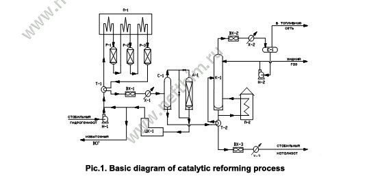
Feed — stable hydrogenate from hydrotreatment block — goes to P-1 pump suction that pumps it to blending T-branch for blending with recycle hydrogen gas, which goes from discharge of recycle compressor RC-1. Feed-H2 gas blend in heat exchanger HE-1 is heated by effluent from R-3 reactor, then is heated in the first section of F-1 furnace and enters R-1 reactor. Then it is heated in the second section of F-1 furnace and goes to R-2 reactor and then it goes to the third section of F-1 furnace and enters R-3 reactor. R-3 reactor effluent gives a part of its heat to the gas-feed blend in HE-1 heat exchanger, then is cooled in an air cooler AC-1, water cooler WC-1 and enters S-1 gas separator. Hydrogen gas separation from liquid product — unstable catalysate — takes place here. Hydrogen gas from S-1 separator goes for removal of excess moisture to D-1 adsorber (or omits it via bypass) and enters recycle compressor suction RC-1, which delivers it again for blending with the feed.
Excess H2 gas goes to hydrotreatment block or to hydrogen line of the refinery. Unstable catalysate from S-1 separator is heated in HE-2 heat exchanger by stable catalysate stream and enters the middle of C-1 column for stabilization, i.e. separation of gaseuous hydrocarbons dissolved in it. Light hydrocarbons up to butanes are released as overhead vapours of C-1 column. The vapours are cooled and condensated in an air cooler AC-2 and water cooler WC-2 and enter reflux drum RD-1. Liquid product from RD-1 enters pump P-2 suction, which pumps it to a top tray of C-1 column as cold reflux. Balance excess is removed to GFU or LPG storage as a liquid gas. Uncondensed gases from RD-1 drum are released to fuel network.
Reforming stable catalysate is withdrawn as bottom product of C-1 column, passes through HE-2 heat exchanger, then is cooled in an air cooler AC-3, water cooler WC-3 and is delivered to the storage as the end product. Heat supply to the bottom of C-1 column is performed by means of circulation of the stable part of catalysate through F-2 furnace under the bottom tray of the column. In order to compensate chlorine loss from the catalyst surface the diagram involves pre-dosed supply of chlororganic compound solution to the first reactor inlet or to each reactor. In order to support the water-chlorine balance pre-dosed supply of water to the reactor block, involving the possibility of separate supply to each reactor, is also included to the scheme.
For the catalyst sulfurization at start-up period the scheme involves pre-dosed supply of organosulfur compound solution to the reactor block. The diagram also involves chlororganic compound supply to each reactor for reforming catalyst reactivation.
Table 2. Reforming units for production of motor gasoline (as per typical projects)
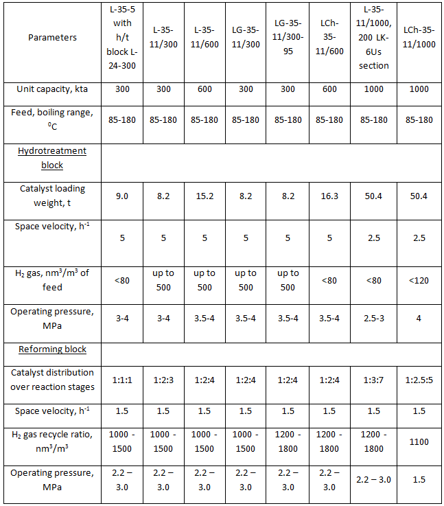
Catalytic reforming units designed for production of motor gasoline component consist of two blocks — hydrotreatment and reforming block. There is an exception — unit L-35-5/300. This unit, being the first commercial reforming unit, was originally designed as a separate catalytic reforming block. This unit is operated together with a standalone typical hydrotreatment unit L-24-300.
Table 3. Catalytic reforming units for production of aromatic hydrocarbons (as per typical projects)
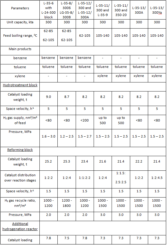
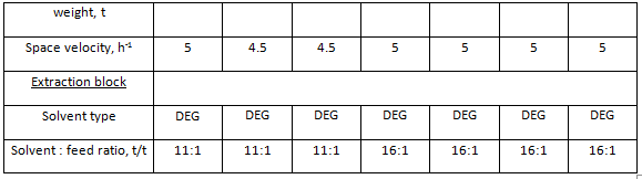
Catalytic reforming unit for production of aromatic hydrocarbons is a much more complex process system. Beside hydrotreatment and reforming blocks, this unit also includes a block of aromatic hydrocarbons extraction from reforming catalysate and precise fractionation block for aromatic extract fractionation and production of commercial aromatic hydrocarbons. A brief description of main types of reforming units for production of motor gasoline component is presented in Table 2. A brief description of typical reforming units for production of aromatic hydrocarbons is presented in Table 3. The submitted data identify the units according to information adapted from typical projects.
Table 4. System volume of reforming units
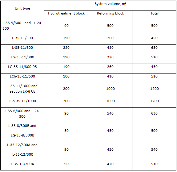
System volumes of hydrotreatment and reforming blocks are presented in Table 4. These data are necessary for calculation of H2 gas and commercial nitrogen flowrate for the periods of unit start-up and catalyst regeneration. Main process flow diagrams of hydrotreatment and reforming blocks are nearly identical. Although there are some differences mainly in instrumentation of separate unit blocks, especially blocks of stabilization of unstable reforming catalysate. Units designed for production of high-octane motor gasoline component are characterized with increase of feed capacity from 300 kta up to 600 - 1000 kta driven by the necessity to increase production of high-octane motor gasolines. All units designed for production of aromatic hydrocarbons had the same feed capacity — 300 kta. Units designed for high naphthenic feed processing had reactor blocks consisting of four reactors — four reaction stages. Those are such units as L-35-12/300, L-35-12/300А and L-35-13/300А. The rest units of the type had reactor blocks consisting of three reaction stages.
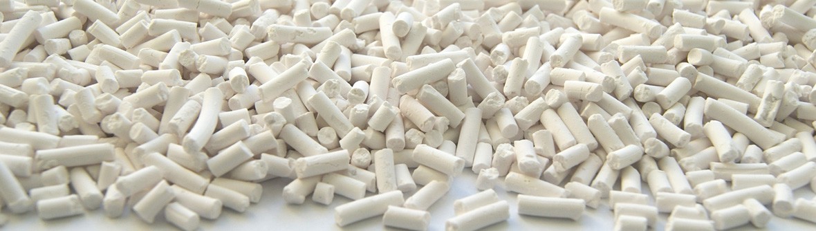
Reforming catalysts
Catalysts based on platinum uniformly dispersed on alumina support promoted with chlorine (rarely with fluorine) are used in catalytic reforming. The nature of active surface of reforming catalysts is based on the bifunctional model of their activity proposed by Miles in 1953. Platinum dispersed on the support surface is a catalyst for hydrogenation-dehydrogenation reactions, and the support — halogenated alumina — is the catalyst for acid-base reactions, i.e. isomerization, cyclization, cracking.
The latest studies have showed that a part of highly dispersed platinum, impregnated on the support, does not correspond to metallic platinum characteristics in terms of its physical, adsorptive, and chemical properties. Such platinum is called electron-deficient and is designated as Ptσ, unlike the metallic platinum designated as Pt?. Specific feature of electron-deficient platinum is its ability to form steady chemisorptive bond with water molecules. According to this feature, all surface platinum atoms on the catalyst are divided into two states: Pt? and Ptσ. The same specific feature of electron-deficient platinum allows estimating its amount on the catalyst surface.
The main specific feature of electron-deficient platinum Ptσ is its high activity in dehydrocyclization reaction of paraffin hydrocarbons — the basic reaction of naphtha catalytic reforming. The rate of paraffin hydrocarbons dehydrocyclization reaction in presence of Ptσ is 10-15 times higher than the rate in presence of Pt? metallic platinum. Electron-deficient platinum Ptσ is a part of surface complexes PtClxOyLz that are the products of strong interaction between platinum precursor and surface groups and defects of γ or η alumina — a basic support for reforming catalysts. Maximal dispersion, platinum ionic conditions, presence of L ligands connected with the support, absence of Pt-Pt bond, high tolerance to sintering — they are all the specific features of Ptσ state. Linear dependence between the rate constant of paraffin hydrocarbons dehydrocyclization reaction and Ptσ content in the catalyst is defined. It allows attributing Ptσ to active sites of paraffin aromatization that have a range of properties responsible for high activity and selectivity in the composite reaction of paraffin hydrocarbons dehydrocyclization.
Developed technologies for production of modern reforming catalysts are aimed at production of catalysts with maximum content of electron-deficient Ptσ. Most active and stable commercial catalysts contain up to 55% of Ptσ of the total platinum content in the catalyst.
Most of commercial reforming catalysts are produced with γ-Al2O3 as a support due to its high thermal stability.
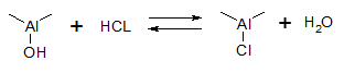
In order to enhance and control acid function of alumina it is promoted with a haloid — fluorine or chlorine. Fluorine-containing catalysts are rarely applied and in such cases when reforming process is performed without feed pre-hydrotreatment or under high moisture conditions. Major amount of reforming catalysts are produced on the basis of chlorinated alumina. The advantage of chlorinated alumina catalysts is a possibility to control chlorine content on the catalyst surface and, therefore, its acidity level under operating conditions. It is explained by the fact that chlorine is a dynamic promoter; it has a weak bond with the support surface and is easily replaced with water hydroxyls.
Chlorine amount on alumina surface is defined by reaction equilibrium:
This fact defines the necessity to maintain a certain concentration of water vapors over catalyst surface during operation. Optimal chlorine content in the catalyst is present at this concentration, which, as a rule, makes 0.9-1.2 wt.%. Chlorine content on the catalyst surface is a function of water : chlorine molar ratio in the reaction zone, Al2O3 surface area, and strength of chlorine containment on the catalyst surface.
Chlorine plays an important role in formation of active catalyst surface, as well as in formation of surface complexes that provide stable catalyst operation in severe process conditions. Approximate composition of such surface complexes is the following: PtσnClxOyLz, where σ=2; n≥1; x+y+z≤4. S ions or hydrocarbon radicals may act as L ligands (reaction medium effect). Finally, recovery of high platinum dispersion on the support during platinum catalyst reactivation is impossible.
Nowadays modified bi- and polymetallic reforming catalysts based on chlorinated alumina containing other elements of periodic system along with platinum are used in commercial practice. Rhenium, stannum, titan, germanium, iridium, lead, zirconium, manganese are modifyers for reforming catalysts.
The main advantage of modified polymetallic reforming catalysts is high stability expressed as much lower activity decrease in process conditions than that of monometallic platinum catalysts.
As the main reason of reforming catalysts deactivation in the reaction cycle is their coking, increase of stability during introduction of modifying metals is due to their influence on coking. Nature of this influence and its mechanism depend on the nature of the modificator applied.
Rhenium modified platinum alumina catalysts — platinum-rhenium catalysts, in some cases having additional third component, are wide spread in commercial practice.
Information of this chapter is given exclusively for a reference purpose. You can find information about SIE Neftehim, LLC's products and services in Developments and Services chapters.
